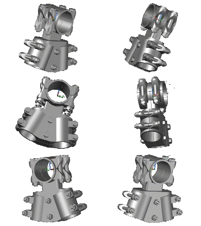


Note: 3D graphics powered by the jsc3d project under the terms of the MIT license.
“Scientists study the world as it is,
Engineers create the world that
never has been.”
–Theodore von Kármán
A 2D View of a 3D World
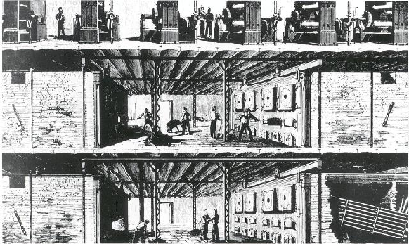
Since Edison designed his Pearl Street station in 1882, engineers have had to contend with the presentation of their design on paper -
Today, we have one advantage that Edison lacked -
Why 3D?
Why make such a drastic change in the design process?
- Reduced design cycle -
The substation design is prepared completely in the plan view. All elevation (section) views are then generated from the plan view. Changes to the design on the plan level are easily reflected in the elevations with minimal hours expended. This results in fewer design errors encountered during construction.
- Reduced construction costs -
The more accurate design inherent in the 3D process results in fewer conflicts, fewer errors during construction and reduced change orders in the construction process.
- Reduced total project cycle cost -
Overall project cost is reduced as a result of the reduced design cycle and reduced construction cost.
- Increased operation safety -
3D design allows the engineer to check for adequate clearances for the operation of equipment such as switches and fuses.
If it ain’t broke…
In a traditional design, there are five major steps that must be taken to develop the plan and elevation (section) drawings.
- First the layout of the Plan View must be developed. This is accomplished by dropping 2D blocks onto the drawing. Bus connections must then be drawn between structures and equipment.
- Next various Elevation and Plan drawings (e.g. foundation and cable and conduit drawings) necessary to convey the design to the material provider and contractor must be defined.
- Then the Elevation and Plan drawings must be drawn. These must be dimensioned and checked carefully against the Plan View for consistency and accuracy.
- The drawings must then be checked for conflicts, resolutions determined and modifications made to both Plan and Elevation drawings affected by the conflicts.
- Lastly, a detailed Bill of Materials must be prepared. This requires a meticulous count of items cross referencing the Plan and Elevation views.
If any changes are made to the plan view, one or more of the elevations must be checked and possibly modified. Likewise, changes to the elevations may result in modifications to the plan. And in all cases, conflicts must be reviewed and resolved.
 Get the Vision
In a 3D design, the steps are similar, but there are some major differences.
- Again, initially the Plan View must be drawn. This is accomplished by dropping 3D structures onto the drawing. The bus and connections are added utilizing specific apps. Conflict determination and resolution are conducted as the design unfolds.
- The Elevation Views are defined and then generated by the CAD software from the 3D model using the SectionPlane and SectionPlanetoBlock commands.
- Elevation and Plan views are arranged in Paperspace and dimensioned. Elevation dimensions must be checked for changes made to the 3D plan view.
- From the 3D Plan View, a detailed Bill of Material can be automatically generated. This is possible because the 3D Plan contains every structure, bus, device, connector and fitting.
Subsequent changes made to the 3D plan view can easily be reflected in the elevation views using the SectionPlane and SectionPlanetoBlock commands.


A New Vision

3D graphics powered by the jsc3d project under the terms of the MIT license.