


Note: 3D graphics powered by the jsc3d project under the terms of the MIT license.
“Scientists study the world as it is,
Engineers create the world that never has been.”
–Theodore von Kármán

Sag Template Method
Section 10.3 of the RUS Bulletin 1724E-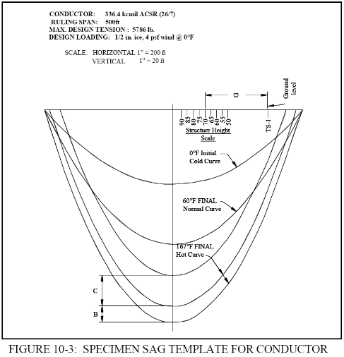 Shown here is a copy of Figure 10-
Computer Aided Design
I first used this approach when I began my career back in the early 70s. And I continued to use it for 20 odd years. In the Oct 1990 issue of Cadence Magazine, Robert Zipprich presented an AutoLISP program, Cat.lsp, which generated a true conductor catenary curve based on the horizontal tension and weight per foot of conductor. I played around with this program but did not get a chance to apply it until I returned to Jackson Energy Authority in 1994.
We had a 46kV line to extend along the Hwy 45 By-
Using the generated profile, I used a modified version of Cat.lsp to spot the poles based on ground clearance. This still required that I generate a “template” block that I could move horizontally from pole to pole to visually locate and size the next pole. I then used Cat.lsp to draw the sag curves for the chosen pole sizes and locations.
Enter PSSAG
After retirement I spent a lot of time developing the 3DToolBox -
The PSSAG approach differs from the RUS method in one way. RUS recommended that a line be drawn parallel to the ground line and offset vertically by the ground clearance distance. (Ironically while this is quite tedious for a drafter, it is quite easy in AutoCAD.) Instead of the offset ground line, PSSAG uses an offset SAG line. The main advantage is that the clearance can easily be adjusted for individual spans.
PSSAG does not incorporate structural or mechanical design functions for line design. The user must develop specific design parameters such as conductor sag/tension characteristics, minimum pole height and class and structure type. Of particular application to the PSSAG program is the development of “Minimum Weight Spans” for initial sag for uplift and insulator swing and “Maximum Weight Spans”for final loaded sag for insulator/crossarm maximum allowable loading. This is described in detail in Chapters 7 and 9 of the RUS Bulletin.
The Program
The Program is contained in a single MS VBA for AutoCAD file and requires no installation procedure other than AutoDesk’s free VBA module. The only requirement in the drawing is that the ground line be placed on a layer named Ground. (I suggest that the Ground layer be set to Locked to eliminate accidental deletion of the ground line.) Instructions for loading and running the program are shown below.
The main PSSAG form includes selections:
- Structures -
List the Structures defined in the Setup file. Selecting the Structure type will define the next Pole inserted. - Pole Hgt & Class -
The selected Poled Hgt and Class will be assigned to the next Pole inserted. - Cat Const (k) -
The selected k value will be used for the next catenary curve generated (via Sag, AutoSag or AutoDesign). - Pole No -
Pole number assigned to the next Pole inserted. This number is auto- incremented when a Pole is inserted. However, it is not decremented on an Undo or if a Pole is erased. The Up/Down button will change the number one digit at a time. - Show Span -
If checked, the Span between poles will be shown with the next catenary generated. However, AutoSag will always generate a clearance line and span on the “temp” layer. - Ground Clearance -
If checked, the ground clearance line will be shown with the next catenary generated.
The following commands are used to aid the user in spotting, moving and replacing poles:
- Pole -
Creates a pole with the selected height and structure type and allows the user to drag it to a location. The Pole will be assigned the number in the Pole No box and the Pole No box will be incremented.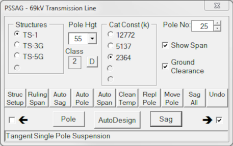
- AutoDesign -
Combines Auto Sag and Auto Pole allowing the user to quickly add poles that provide required ground clearance. AutoDesign greatly speeds up the design process. - Sag -
Generates catenary curves from one pole to the next. Selecting the Cat Constant for the Initial conductor design parameters allows the user to check for uplift, conductor swing etc. Selecting the Final design constant allows the user to generate sag curves for ground clearance. If the Show Span box is checked, the program will generate a span distance text between the adjacent poles. If the Ground Clearance box is checked, the program will generate ground clearance line based on the Ground Clearance. - Struc Setup -
Opens the Design Data form to define the Structures and Conductors (see below). - Ruling Span -
Calculates the actual Ruling Span of the pole layout and summarizes the Structures by type and pole height. - Auto Sag -
Generates two catenary curves - the ground clearance line and the conductor sag line - Auto Pole -
After generating the sag lines, Auto Pole locates a pole at the point at which the lowest conductor attachment point lies on the conductor sag and the pole base touches the ground. - Auto Span -
Locates poles that are equally spaced (equal spans) between two points. - Clean Temp -
Deletes the Auto Sag lines and span distances generated by Auto Sag and Auto Pole on the “temp” layer. - Repl Pole -
Replaces the selected pole with the pole height and structure type currently selected. The Pole retains its Pole No. - Move Pole -
Moves the selected pole with a grip at the base of the pole. - Sag All -
Generates sag curves for all positions on the poles for the entire length of the Project. It will delete all existing curves. - Undo -
Undoes previous commands.
Clicking the Struc Setup button brings up the Design Data form. With this form the user defines the following:
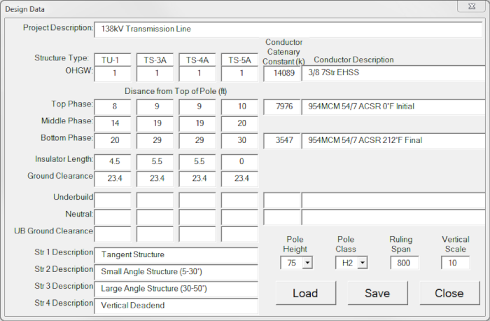 Project Description -
A brief description of the Project. This appears in the caption of the PSSAG form. - Structure Type -
Up to four types can be defined for the project based on the Distance from the Top of the Pole to each conductor attachment point. - Top Phase -
Distance to the top phase. Initial conductor sag is shown at the Top Phase position. - Middle Phase -
Distance to the middle phase. If the Middle and Bottom Phases are at the same location, enter 0. - Bottom Phase -
The lowest phase of the structure. This attachment point will be used to determine pole height based on conductor sag and clearance. - Insulator Length -
The insulator length can be added for suspension structure types. - Ground Clearance -
The NESC clearance from the Bottom Phase to the ground. It generally includes an extra foot for survey errors. It is used to generate the ground clearance line. - Underbuild -
Location of an UB circuit if present. - Neutral -
Location of a Neutral conductor if present. - UB Ground Clearance -
Clearance between the UB or Neutral and ground. - Cond Catenary Constants (k) -
Constants associated with the various conductor levels. The value of k is taken from conductor sag/tension data and is the horizontal tension in pounds divided by the weight per foot of the conductor. - Conductor Description -
Description associated with each conductor. - Pole Height -
The minimum (or standard) pole for this project based on the distance from the Bottom Phase plus the Insulator Length, plus the Ground Clearance plus the calculated conductor sag for the Ruling Span. - Pole Class -
Selected based on the transverse loading analysis of standard pole. - Ruling Span -
The project design Ruling Span. - Vertical Scale -
The ratio of the horizontal to vertical scale, usually a factor of 10. This value has no relationship to the plotted scale of the final drawing.
Program Installation and Running
To run the program, load the PSSAG.dvb file using the Tools>Macro>VBA Manager menu. Once loaded, at the command prompt type -
Click the Struc Setup button. Again a File Open form will be presented and again click Cancel. A blank Design Data form will be opened. Once it is filled out, saved and closed, the data will populate the PSSAG form.
The video below demonstrates the ease with which PSSAG assists in spotting poles. I suggest that you click the Watch on YouTube button at the bottom left and watch it in full screen mode.

